

Polyurethane Flame Retardant Factory Processes That Deliver Safer High-Performance Materials
2026-11-21
Most conversations about polyurethane flame retardants stop at the additive. But inside a modern factory, the real difference is made earlier: in reactor control, dispersion, and how flame-retardant chemistry is locked into the polymer matrix without turning finished parts brittle. That is where Fortune has focused its process engineering. In this post, we walk through the production steps that separate a genuinely safer, high-performance material from one that merely passes a spec sheet.
What Happens Before Flame Retardants Enter the Polyol Mix
Long before a flame retardant reaches the blending vessel, the base polyol stream is pulled from storage and brought to a controlled temperature. Operators check moisture content, acid number, and viscosity against the batch sheet because small deviations in any of these can change how the foam builds later. Inline analyzers and grab samples both get used, and if the polyol is too cold or carrying too much water, it is held back until conditions settle into the working range.
On the additive side, the flame retardant itself often needs attention before it can be introduced. High-viscosity liquids may be preheated in a day tank or recirculated gently so they do not slug into the mix, while solid grades are pre-dispersed in a small amount of carrier polyol to break up clumps. The goal is a uniform feed rather than a sudden dump, and the agitation speed on the premix vessel is adjusted by what the operators see during the first few minutes of blending.
There is also a short compatibility check that happens away from the main line. A bench-scale mixture of the candidate polyol, water, catalysts, surfactant, and flame retardant is made and watched for phase separation, gelling, color drift, or unusual viscosity rise. If the lab batch stays stable through the expected pot life and early cure window, the formulation is cleared to move into the production mixer. Only after that step does the flame retardant actually enter the polyol mix.
Mixing Energy Windows That Keep Additive Dispersion Uniform
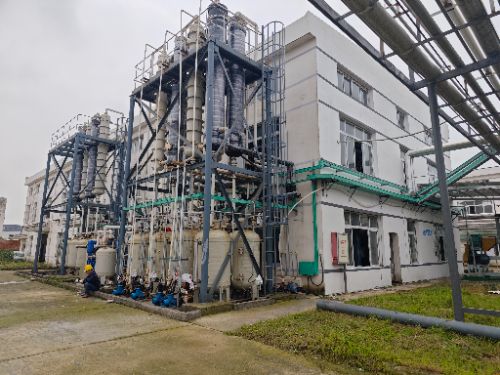
Additives rarely fail because the chemistry is wrong; they fail because the energy input during incorporation drifts outside a fairly narrow band. When the mixer runs too gently, pigment or stabilizer particles hold onto their agglomerates and the final product shows local concentrations, streaks, or early settling. On the other hand, pushing the mix too hard can have the same visual result through a different route: the additive structure may be torn apart, heated, or forced into regions that already have enough, so the dispersion appears uneven even though the average loading is correct.
The useful window is not a single setpoint but a range where shear, temperature, and residence time stay balanced. In practice this means watching torque curves and batch-to-batch viscosity shifts rather than relying on rpm alone. If the torque trace flattens too early, the energy may be too low to break loose dry clumps. If it stays high and then drops sharply, the batch may have crossed into over-mixing, where particle size can climb again through re-agglomeration or emulsifier depletion. Staying inside the window gives repeatable color strength, surface smoothness, or mechanical properties without having to adjust formulation every run.
A narrow energy window also matters when a line changes raw materials or batch size. Slightly finer powders, a different carrier resin, or a larger bowl can shift the point where uniform dispersion actually occurs. Rather than copying a fixed speed from an older recipe, it is more reliable to map the response to specific energy input or shear history and then keep each batch within that measured band. That way, additive dispersion stays uniform not because the mixer settings look familiar, but because the mechanical work per unit volume remains inside the range the additive can accept.
Reactive Phosphorus Builds a Safer Polymer Without Stiffening the Foam
Conventional flame retardants often force foam formulators into a trade-off: add enough additive to meet fire safety targets and the polyurethane matrix loses its suppleness, developing a board-like feel that customers reject. Reactive phosphorus takes a different route. Instead of dispersing solid or viscous retardants through the cured network, a phosphorus-bearing polyol is copolymerized into the backbone, so the element sits where it can interrupt combustion without contributing the rigid segments or filler-like interactions that normally stiffen the foam.
During a fire the incorporated phosphorus promotes char formation at the polymer surface and releases radicals in the gas phase, both of which slow flame spread and reduce heat release. Because the phosphorus is chemically bound, it does not migrate to the foam surface over time or leach out under humidity and abrasion. The soft-segment mobility remains largely intact: compression set, resilience, and cell openness stay close to those of an unmodified foam, while cone calorimeter data show lower peak heat release and less smoke.
The practical advantage shows up in seating, acoustic panels, and thermal insulation where comfort or flexibility has to survive alongside stricter fire codes. Manufacturers can run the reactive polyol on existing low-pressure dispensing lines with only minor changes to isocyanate index and catalyst package, avoiding the viscosity spikes and settling problems that often accompany high loadings of additive flame retardants.
Balancing Zinc Borate and Alumina Trihydrate for Low-Smoke Performance
Finding the right ratio between zinc borate and alumina trihydrate usually starts with smoke density, but it rarely ends there. Alumina trihydrate suppresses smoke by releasing water through an endothermic breakdown, which cools the polymer and dilutes combustible gases. Zinc borate works later in the burning process, sitting in the condensed phase and helping to form a more coherent char while also cutting afterglow. When the two are combined, the smoke reduction is not simply additive. Replace too much ATH with zinc borate and the char can become rigid enough to crack open under heat, exposing fresh polymer. Leave the ATH share too high and the compound may need filler loadings that hurt elongation and processability before smoke targets are met.
A more practical way to balance them is to fix the total filler content first, then shift the zinc borate portion upward in small increments while watching cone calorimeter data and vertical burn ratings together. In many halogen-free EVA and polyolefin compounds, a zinc borate range of about 5 to 15 parts per hundred resin, paired with ATH at the higher end, produces a noticeable drop in peak smoke release without automatically sacrificing UL 94 performance. The exact balance changes with particle size, coating, and melt flow. Finer ATH grades tend to pack better around the zinc borate particles and improve char integrity at lower overall filler levels. Coarser grades can create pockets where smoke escapes before the char closes, so the same ratio can behave very differently in two compounds.
Processing conditions deserve as much attention as the formulation ratio. Alumina trihydrate begins to lose water near 220°C, and pushing the melt temperature too high creates micro-voids and rough surfaces before the part ever sees a flame. Zinc borate is more thermally stable but can still shift the rheology enough to change how the compound fills thin sections. A low-smoke formula that passes in the lab will fail on the production line if the temperature profile is overly aggressive. Balancing the two additives therefore means adjusting both the recipe and the extrusion or molding window until the compound keeps its smoke performance without turning brittle, frothing, or losing surface quality.
Why Cure Oven Profiles Decide Whether Char Holds Up Under Heat
The shape of the cure curve dictates how the resin skeleton forms before it ever has to face pyrolysis. Spend too long in the low-temperature band and volatile byproducts leave through a half-formed network, creating the kind of pore channels that become initiation sites once real heat arrives. Push the high-temperature ramp too early and the surface seals over while the interior is still trying to release gases. Those defects don't disappear after curing; they sit dormant until the char layer is asked to perform.
Ramp rate matters in a way that steady-state numbers miss. A fast climb can lock the outer few microns into a dense, glassy shell while the material underneath remains under-crosslinked or unevenly reacted. The mismatch in thermal expansion between that shell and the softer interior is exactly where cracking starts when the part sees a sudden heat spike. Slower, stepped profiles give the crosslinking reactions enough room to complete in sequence, producing a char that feels less like a crust and more like a continuous carbon network.
Peak temperature and hold time only work as a pair. If the peak is too low, the polymer never reaches the aromatic conversion needed for a stable carbon skeleton, so the char is present but structurally weak. If the hold runs too long, oxidative damage and excessive shrinkage introduce microcracks that later grow under thermal cycling. The profiles that hold up are the ones tuned to the material's actual mass-loss zone, where the char remains coherent after repeated thermal shocks instead of just looking intact on the surface.
The Final Heat Release Check That Catches Formula Drift Early
Most teams treat the final heat release check as a formality, but it’s the one pass that exposes what earlier inspections miss. After the car comes up to temperature and then cools, fasteners settle, hoses shift, and tiny seeps turn into visible trails. Walking the car with a flashlight and a torque wrench right after that last warm-up cycle tends to reveal loose clamps at the radiator, weeping banjo fittings, or a brake line that moved closer to the exhaust than anyone noticed on the build table.
The value comes from reading the heat signature rather than just checking boxes. Discoloration around the turbo, melted zip ties near the downpipe, or a clutch line that feels softer after repeated engagement all point to problems that would only appear halfway through a tandem run. Catch them here, and the fix is a quick adjustment. Miss them, and the same issue turns into a fire, a dropped clutch, or a loss of brakes when it matters most.
A good final check also records baseline pressures and fluid levels while the car is still warm, because that’s the condition it will be in on grid. If the coolant bottle drops more than expected after the fans cycle or the power steering reservoir shows foam, the car isn’t ready. That last walk around is less about confirming what’s right and more about hunting for what’s about to go wrong.
FAQ
The main difference lies in additive dosing precision and thermal controls. Dedicated lines often use closed-loop feeders and staged mixing zones so that phosphorus- or nitrogen-based retardants disperse evenly without degrading the polymer backbone.
They tend to adjust the isocyanate index and catalyst package rather than simply raising additive loadings. This helps preserve tensile strength and elongation while the char-forming chemistry handles the fire side.
Inline rheology readings, temperature logs at the mixing head, and periodic nitrogen content analysis give the clearest early warning. If viscosity drifts outside a narrow band, the distribution of retardant particles usually suffers first.
Adding flame retardants before water or blowing agents can create local viscosity spikes and uneven cell structure. A staged sequence lets each component wet the polyol phase properly, reducing rejected batches and burn-test variability.
Curing too hot can volatilize part of the flame retardant package or cause it to migrate toward the surface. A controlled ramp profile locks the additives into the polymer matrix, improving both char formation and long-term stability.
Many rely on cone calorimeter screening, limited oxygen index tests, and thermal gravimetric analysis on small coupons pulled from the line. These results correlate well enough with larger regulatory burns to catch problematic batches early.
Yes, if the formulation is tuned for the application. For example, mineral-based synergists can maintain abrasion resistance while reactive phosphorus compounds keep the flame rating intact, so the material does not have to sacrifice toughness.
Conclusion
Before a batch ever reaches the main reactor, incoming flame retardants are screened for particle size, moisture and thermal stability; anything that clumps or releases volatiles too early is rejected or pre-dried. The polyol side is held just warm enough to keep viscosity workable, then additives are introduced through a mixing window defined by shear rate and temperature rather than fixed time. Going too hard shatters solid synergists, while going too soft lets phosphorus-rich droplets settle. Operators watch the torque curve and adjust blade speed inside that window so dispersion stays uniform without cooking the blend. Reactive phosphorus then takes over at the molecular level: it grafts into the polyurethane backbone during polymerization instead of sitting in the foam as a migratory package. That keeps the cell structure soft and open while still forcing char formation once a flame hits.
For low-smoke performance, zinc borate and alumina trihydrate are balanced by loading and particle size, not just total percentage. Alumina trihydrate cools the flame front and releases water, zinc borate strengthens the glassy char, but too much of either can make the foam brittle or raise smoke obscuration. Cure oven profiles are then tuned so the outer skin does not over-cure before the core reaches full crosslink density; a steep ramp can leave weak, half-formed char that collapses under heat. Finally, a small-scale heat release check on every production lot compares peak and total values against a narrow baseline. If the curve drifts upward even a few points, the formula or mixing record is pulled before the material ships, so the plant catches drift early instead of waiting for a full-scale burn test.
Contact Us
Contact Person: WANG SIHAI
Email: [email protected]
Tel/WhatsApp: +86-13815295628
Website: https://www.fortunechemtech.com/index_en.html