

Top Industrial Vibration Motor Options for Heavy-Duty Applications
2026-11-02
Industrial vibration motors are the silent workhorses behind heavy-duty processes—think aggregate screens, foundry shakeouts, and bulk material feeders. Yet pick the wrong one, and you're facing premature failures, costly downtime, and endless maintenance. That's why we've rounded up the top options that actually hold up under extreme loads, continuous duty cycles, and harsh environments. One name that keeps proving its worth on the plant floor is Guangling, known for motors that combine brute force with precision balance. Here's what to look for before you buy.
Matching Motor Torque to the Load Profile
Getting torque right starts with plotting the actual load torque across the speed range and duty cycle. Many systems fail because they look only at rated torque, forgetting that breakaway friction, acceleration, and variable process loads all demand more at specific moments. A motor that matches the load profile should handle the peak torque without thermal tripping and still run efficiently at the normal operating point. That means comparing the motor's torque-speed curve not just to one number, but to every segment of the motion or process curve.
Oversizing is a common reaction to uncertainty, but it brings penalties: higher purchase cost, larger footprint, and often worse efficiency at partial load. Instead, a tighter match can be achieved by separating continuous duty from intermittent peaks. If the load requires high torque for a few seconds during acceleration or jam clearance, you may only need a motor with sufficient peak torque capability and a drive that allows short-duration overload. Continuous torque, on the other hand, must be met without exceeding thermal limits over the longest expected run.
In practice, this matching is iterative. Start with a measured or simulated load profile, pick a motor whose continuous torque exceeds the RMS torque of the duty cycle, then verify that its peak torque covers the highest short-duration demand. Watch the corner speed too: if the load needs torque at higher speeds, the motor's field weakening region can become the constraint. A well-matched drive runs close to its rated point during the dominant portion of the cycle, leaving just enough headroom for real-world disturbances.
When to Select an Explosion-Proof Enclosure
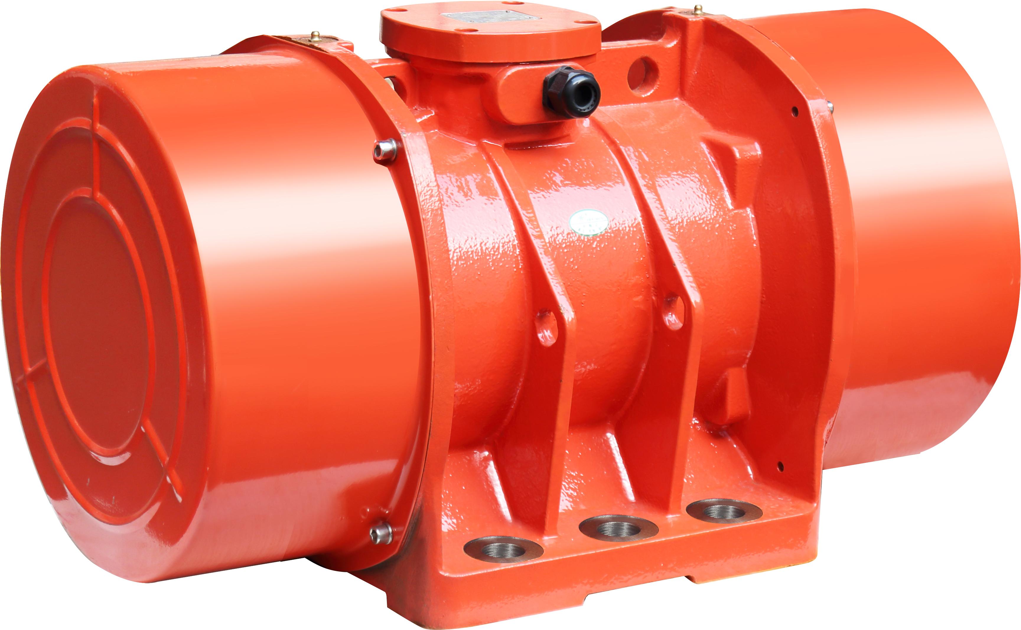
Choosing an explosion-proof enclosure becomes necessary whenever electrical equipment must operate in an environment where flammable gases, vapors, or combustible dusts are present in sufficient concentrations to ignite. Rather than trying to prevent every possible internal spark or heat source, these enclosures are engineered to contain an explosion if it occurs and prevent the ignited gases from escaping into the surrounding atmosphere. This makes them a practical choice in chemical processing plants, refineries, grain elevators, and paint booths, where normal operating conditions can occasionally release hazardous substances.
The decision often hinges on the area classification defined by standards such as the NEC in the United States or ATEX directives in Europe. If a location is designated as Class I Division 1 or Zone 1, where ignitable concentrations exist during normal operation, an explosion-proof enclosure is typically not just recommended but mandatory. Even in Division 2 or Zone 2 areas—where hazardous materials are present only under abnormal conditions—selecting a rated enclosure can offer an extra margin of safety and may be required depending on the equipment's sparking potential or maintenance practices.
Beyond regulatory compliance, opt for an explosion-proof enclosure when total cost of ownership matters. The upfront expense is higher than standard enclosures, but the added protection reduces the risk of catastrophic failures, production downtime, and liability associated with ignition events. In facilities where a single enclosure failure could halt an entire process line or endanger personnel, the robust construction and certified seals of an explosion-proof design often end up being the more economical and responsible long-term investment.
Fine-Tuning Eccentric Weights for Controllable Force
Adjusting eccentric mass isn't about chasing a single perfect number—it's about mapping a range where the force feels intentional rather than accidental. Start by measuring the baseline vibration amplitude at your motor's typical operating speed. Then swap in slightly heavier or lighter offset weights, noting how each variation shifts the amplitude curve. Small changes, often under 5% of the original weight, can produce a surprising degree of control over peak force without destabilizing the entire assembly.
The real trick lies in understanding that eccentric force scales with the square of rotational speed, so weight adjustments act more like a fine trim than a primary dial. If you need a stronger push at lower RPMs, adding a bit more mass at a slightly larger radius usually works better than simply stacking more weight near the shaft. Keep the weights balanced across the axis of rotation—uneven distribution creates lateral wobble that masquerades as increased force but actually wastes energy and wears bearings faster.
For practical tuning, create three test configurations: one with the stock eccentric, one with a 10% reduction, and one with a 10% increase. Run each at the same voltage and record the force output with a load cell or accelerometer. Most systems respond more predictably to weight reductions than to increases, since added mass can push the motor outside its efficient torque band. Lock in the configuration that gives you the widest controllable range, then make micro-adjustments by shifting the weight's angular position rather than its mass whenever possible.
Why Foot-Mounted Designs Excel in Aggregate Handling
Foot-mounted designs hold a key advantage in aggregate handling because they keep the drive assembly close to the ground, which lowers the center of gravity and reduces torque reactions that often loosen housings or crack bases in top-mounted setups. This configuration lets the gearbox and motor sit directly under the load path, so vibration from lumpy materials like crushed stone or recycled concrete gets absorbed into the structure instead of shaking the mounting points apart.
In facilities where spillage, dust, and uneven feed are constant, having the motor and reducer mounted at foot level simplifies inspection and belt changes. Workers can reach lubrication points and check alignment without climbing over the conveyor frame, and the shorter shaft-to-shaft distance means fewer coupling issues when the belt drifts under heavy surge loads. The result is less downtime and fewer surprise failures during peak crushing seasons.
Another practical benefit is that foot-mounted units can be shimmed and realigned on site without removing the entire drive package. Aggregate belts rarely stay perfectly square after months of impact, so the ability to adjust the base in place keeps the belt tracking straight and prevents edge fraying. This flexibility, combined with the inherent stability of a low-profile mount, makes the design a preferred choice for high-tonnage, high-impact conveying work.
Keeping Bearings Cool During Extended Run Cycles
Heat is the quiet killer of bearings in continuous duty. After hours of nonstop rotation, grease starts to thin, oxidation accelerates, and the internal clearance tightens just enough to spike friction. A practical first move is to match the lubricant to the running temperature rather than the startup temperature. Synthetic oils or high-temperature greases with stable viscosity keep a working film when mineral-based options break down. Also resist the urge to pack the housing full: too much grease churns and generates its own heat, which defeats the purpose.
When lubrication alone cannot shed enough BTU, active cooling becomes necessary. A simple forced-air stream directed at the housing can pull away 15 to 25 degrees Fahrenheit in many installations. For hotter processes or high ambient environments, water-cooled bearing housings or a circulating oil loop with a small heat exchanger are far more effective. Pay close attention to shaft temperature as well; if the shaft conducts heat from a hot impeller or dryer, a thermal barrier or insulated coupling can stop that heat from migrating straight into the inner ring.
Monitoring is what keeps a cooling strategy from going blind. Mount a thermocouple or infrared sensor on the bearing housing and record readings at the same load and speed each shift. A gradual upward trend often signals degrading grease, slight misalignment, or increased load before vibration picks up. If the operation cannot include rest periods, consider bearings with greater internal clearance or ceramic rolling elements to tolerate higher thermal expansion without pinching the races. The goal is not just lower temperatures, but a stable temperature that holds steady through the entire run cycle.
Reading Vibration Signatures Before They Become Failures
Every rotating machine carries a unique vibration fingerprint, shaped by its speed, load, bearings, and mounting stiffness. Long before a bearing spalls or a shaft cracks, subtle shifts appear in that pattern—harmonics that flatten, sidebands that widen, or a transient spike that repeats with each revolution. Learning to read those shifts means treating vibration not as a noisy byproduct but as a continuous stream of condition data. The trick is separating meaningful change from the everyday jostle of operation, which demands both consistent measurement points and an ear tuned to what normal actually sounds like for each asset.
One practical approach is to build a baseline from routine walk-around data, then watch for deviations in specific frequency bands rather than overall level. A velocity trend that drifts upward at 1x running speed might point to unbalance, while a growing family of peaks at ball-pass frequencies often signals early bearing distress. The key is to investigate small excursions before they cross alarm thresholds—because by the time a standard vibration limit is exceeded, physical damage has usually already begun. Short, targeted measurements at the same location and under similar operating conditions turn those excursions into early warnings instead of post-mortem evidence.
Interpreting these signatures also benefits from pairing the vibration plot with a simple operational context: was the machine cold-started, lightly loaded, or recently greased? A change that appears alarming on paper may be a harmless thermal effect or a lubrication shift that settles within hours. Conversely, a stable-looking spectrum can hide a developing fault if the measurement is taken at the wrong spot or with a loose sensor mount. The goal is not to predict every failure with certainty, but to catch the machine speaking in its own dialect—and to respond while the repair is still cheap, scheduled, and free of collateral damage.
FAQ
Heavy-duty units typically have reinforced bearings, thicker housings, and higher ingress protection. They are designed to run continuously under high centrifugal force without the winding insulation breaking down or the shaft seizing, which is what usually kills lighter motors on demanding equipment.
Rotary electric vibrators with adjustable eccentric weights are common, but for extreme force or variable speed, hydraulic or pneumatic vibrators can be a better fit. The right choice depends on whether you need constant frequency, variable amplitude, or operation in hazardous locations.
You start with the total vibratory mass and the required stroke or amplitude. Multiply those to find the working moment, then add a safety margin for material buildup and uneven loading. Oversizing slightly is usually less harmful than undersizing, which leads to overwork and premature failure.
Yes. Look for ATEX, IECEx, or CSA certified motors with an IP66 or IP67 rating. These have sealed terminal boxes, anti-static coatings, and sometimes special temperature limits so they do not become an ignition source in dusty or damp processing plants.
Grease the bearings on schedule, but avoid overgreasing because that builds internal pressure. Check the eccentric weight covers for cracks, retorque mounting bolts after the first week, and monitor current draw periodically—an unexplained rise often indicates a bearing issue or misaligned load.
Many AC-powered rotary vibrators are fixed speed if they are direct online, but you can adjust force by repositioning the eccentric weights. For variable speed or continuous force control, you need an inverter-duty motor or a hydraulic drive, which adds complexity but benefits processes with changing feed rates.
Mounting on an unsupported thin plate, using mismatched bolts, or welding brackets that create stress risers are frequent errors. The motor should sit on a machined, reinforced base and be torqued to the manufacturer's specification, otherwise micro-cracks form around the mounting feet.
Brand matters mainly for consistent quality and spare part availability. Lesser-known brands can work, but you need to confirm the motor has genuine heavy-duty features—not just a thicker coat of paint. Ask for a bearing size chart and winding insulation class rather than relying on marketing terms.
Conclusion
Heavy-duty vibration motors thrive when torque characteristics align with the actual load profile, preventing stalls during dense material surges. Rather than defaulting to the largest frame size, engineers compare breakaway torque, running torque, and inertial demands of the hopper or screen. In hazardous environments, selecting an explosion-proof enclosure becomes non-negotiable—not as a generic upgrade, but as a match to the specific gas or dust classification, ensuring motor temperature and spark paths stay contained. Fine-tuning eccentric weights shifts generated force without changing speed, letting a single motor cover multiple process stages from gentle compaction to aggressive discharge. This adjustment also reduces mechanical stress on supporting structures.
Foot-mounted designs remain the workhorse for aggregate handling because their rigid base plates resist lateral shifting and simplify alignment on vibrating screens and feeders. However, sustained campaigns push bearings hard; keeping them cool demands attention to grease viscosity, relubrication intervals, and sometimes auxiliary cooling fins or directed airflow rather than assuming standard seals suffice. Reading vibration signatures early—tracking changes in harmonic peaks or sidebands—turns the motor itself into a condition sensor. A subtle rise in high-frequency energy often precedes outer race damage, giving maintenance crews a window to swap bearings before a catastrophic unplanned stop. By combining these practices, operators narrow down top motor options that survive heavy-duty cycles without overspending on unneeded features.
Contact Us
Contact Person: ZHUO
Email: [email protected]
Tel/WhatsApp: 86-576-86320988
Website: https://www.cnguangling.com